Avoiding the ACIS Error Monster Or How to Build 3D Models that Really Work
You’re hard at work putting the finishing touches on a 3D model when suddenly it won’t shell or the edges can’t blend. On the screen, as if out of the black lagoon of 3D hell, looms the dreaded ACIS Error. Horrors! How was this monster invoked and how can you avoid becoming the object of his evil eye ever again?
While there are a large number of specific conditions that will spawn that demonic creature known as the ACIS Error, most stem from the same three root causes.
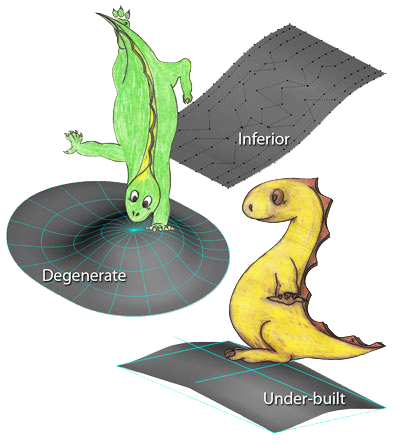
The Three Mortal Sins of Three-D Modeling
The three surface conditions that breed evil within your 3D modeling files are very specific:
- Under-built or exact-built surfaces
- Degenerate surfaces
- Imported inferior surfaces

A little knowledge presented in the following pages will help you avoid all three, and therefore walk in the way of the light, avoiding the dark side that only leads to modeling death.
Be aware that while this article speaks of surfaces, solids for the purposes of this discussion are merely a collection of surfaces, so all of the information applies. Any problem with a solid model would have appeared in a surface modeling program, just one surface at a time.

Some people think that surface modeling software will get things done that can’t be done in a solid modeler. As with any tale of good and evil, there is usually an element of truth and an element of falsehood. It is true that surface models are developed one surface at a time, which promotes the understanding of what works and what doesn’t. In solid modeling, surfaces are handled as a group so if something is wrong, you won’t know which surfaces are the specific problem. Ashlar-Vellum Cobalt, Xenon and Argon all have tools to determine what is wrong with a surface or solid model. What is untrue about surface modeling is that the resulting surface model is always water-tight and manufacturable. Since you can only look at the surface-to-surface interactions, it’s possible for them to look correctly matched and you will assume everything is safe, only to have another monster rear its ugly head in manufacturing, this time as an enormous failure.
Under-built or Exact-built Surfaces—The Bane of Modeling Existence
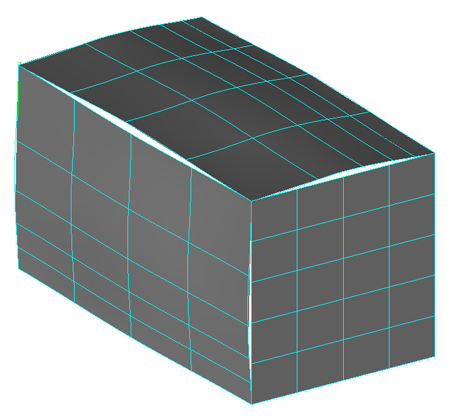
The most common evil in 3D modeling is usually the under-built surface, or one that is built to the exact size and then shrinks when offset. The key problem is that many surface tools, in all brands of 3D modeling software, don’t tell you that you’re constructing a mathematically difficult, if not impossible, situation. They simply assume you know what you’re doing.
The Net Surface tool is one of the most misunderstood and therefore most dangerous beasts because not only does it create under-built surfaces, but it will create a surface with edges that are not where you think they’re going to be. It appears to draw the surface to the curves or wires, but does not. Treacherously it uses the curves like springs to pull the net surface toward it, but the surface “gives” and doesn’t lie along the wires. If you move a curve you’ll see that while the wire influences it, the edge of the curve is not drawn exactly to the edge, leaving a gap that will cause problems downstream.
Then, if you create another surface using the original wire, it won’t actually be touching where you think that it does. Of course, many a knight in shining armor has attempted to slay this dragon by using the created edge instead of the wire to build the new surface. While this works part of the time, there is still a chance for mortal failure because the net surface is an under-built surface and when an offset is applied, it may shrink too much or not expand enough to accommodate the offset.
When a surface shrinks too much in offset, ACIS is required to use it anyway and will attempt to grow the surface. Depending on the original wires, mathematical order and a bit of black magic, it may not be able to grow it and will instead conjure the ACIS Error.
The best defense in this condition is to overbuild the surface and use trimmed surfaces. When ACIS offsets a trimmed surface and it shrinks too much, ACIS looks at the untrimmed surface and can see the way in which the surface needs to grow to mathematically complete the operation.
Degenerate Surface—Beyond the Point of Depravity
While it is possible for Cobalt, Xenon and Argon to appear to create surfaces with zero edges, such as a sphere, or two edges such as a cylinder, in reality, by the NURBs definition, each have four edges.

All surfaces by definition are 2D and by convention the directions are called U and V local to the surface, not X and Y which are global to the 3D object. Turning on the isoparms show the U and V directions. Look carefully. When the U and V lines converge it is an edge not a point. If any points along an edge of a surface are too close together, the surface is called degenerate.
Degenerate surfaces are typically caused by using surfacing commands incorrectly, such as misuse of the sphere and cone primitives, or not understanding the ramifications of surface tools such as Skin, Ruled, Two-rail Sweep and Lathe, or solid tools like Lathe, Two-rail Sweep and Section Solids.
This can cause destruction in older Computer-aided Manufacturing and Computer Numerical Control Machining systems which simply can’t calculate degenerate surfaces. It is also a major source of evil within Cobalt, Xenon and Argon when the degenerate surface interacts with another surface at the point of degeneration.

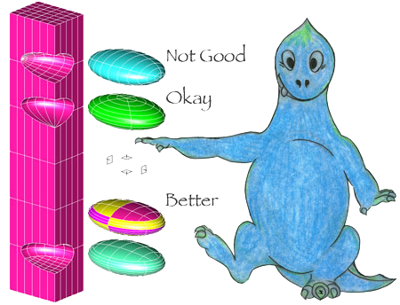
For example, examine an ellipsoid showing the isoparms. Where the isoparms converge on the ends are potential trouble spots as these are infinitely small edges, not points.
Therefore, when you subtract the ellipsoid from a block in such a way that the degenerate edge lies along the edge of another surface this creates a potential hazard.
To defend against this situation, redefine the ellipsoid so that the degenerate edge no longer lies along the other edge exactly.
Imported Inferior Surfaces—Those Foreign Devils
Models imported from other modeling software may be inferior for several reasons. They may be under-built, they may contain degenerate surfaces, or they may be “heavy,” or contain too much extra data that is perhaps in conflict with itself.
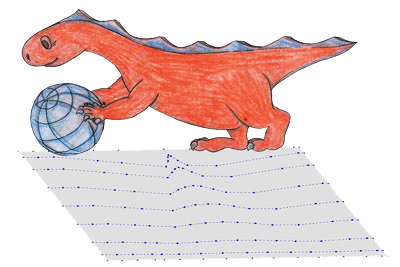
There is a special case of degenerate surfaces where an entire edge does not come to a point, but somewhere in the surface there is a mathematical point that you may not see, causing the smooth surface to become “bunched,” as shown in the illustration.
To guard against evil when importing a foreign file, use the Verify tool in Cobalt, Xenon or Argon to report and attempt to repair grossly bunched surfaces. Another good defense is the Simplify Objects tool, which looks at the NURBs and turns them into analytic surfaces, simplifying the definition of the surface. The Rebuild tool rebuilds complex surfaces into simple NURB surfaces if possible.
Slay the Monster, Rescue the Model, Be a Hero
The green-eyed ACIS Error monster no longer has to plague your existence, ravage your models and wreck havoc in your designs. Once you understand these guidelines and avoid these mortal sins you have complete flexibility within Cobalt, Xenon and Argon to create anything you want in any way you choose.