Export Nasties from Other CAD Programs
Our tech support department is often asked, “Why is this 2D file, which looks so simple, such a big and complicated mess when imported?” The answer is in the way that 2D file was exported from its original source.
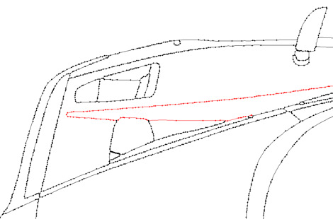
Sometimes when opening a simple looking file imported from another CAD, 3D modeling or other drawing program, what was intended to be perhaps a dozen arcs or splines suddenly becomes tens of thousands of tiny line segments or points. This is not in any way an Ashlar-Vellum bug. Graphite, Cobalt™ or any other members of the Ashlar-Vellum team is merely reading what it has been given. The systematic tessellation, or breaking into tiny line segments, is the fault of the source program from which it was exported.
Most 2D files with this problem got this way by experiencing one of the following four issues originating in their source drafting, modeling or drawing program:
- Tessellation during 3D to 2D conversion
- Tessellation during export
- Tessellation during printing to PDF
- Tessellation during creation by an imprecise modeling program
Each one of these methods has difficulties for different reasons and each one has different solutions.
Tessellation During 3D to 2D Conversion
The problem is that many 3D modeling programs assume that the 3D to 2D conversion is just for printing so it creates a drawfile which designated the arcs, splines and lines as tiny line segments or dots. This is exactly what the printer wants. Unfortunately, anyone who wants to reuse that 2D data in another program is sunk.
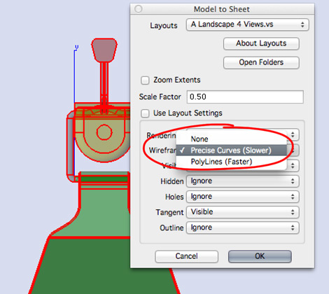
Solutions: Use precision settings for the 2D drawing. For example, in Cobalt, Xenon™ and Argon™, this is done during the 2D Sheet View creation or editing process. Be sure to select the Precise Curves option for the 3D higher order entities to stay intact, rather than faking it with the imprecise (but faster to calculate) Polyline option.
Most, but not all, competitive software offers these settings. Should you be using software that does not, optionally you can use a different product for the conversion. For example, bring an SAT file into Cobalt then export it as a DWG or PDF file as needed.
Tessellation During Export
The reason the file is big and cumbersome is simply bad export technology on the part of the source CAD program. Some competitive drafting, modeling and drawing programs merely export in the lowest common denominator which are tessellated line segments. This is simply laziness on the part of the software programmers who only want to write one subroutine instead of the 50 or so necessary to send the geometric equations for all of the variations, like a 3-point arc to 3-point arc, through-point spline to through-point spline, or center-point circle to center-point circle.
Solution: Contact the manufacturer of the original software for suggestions on a different format with a more precise data export.
Tessellation During Printing to PDF
The Print to PDF process always tessellates the geometry due to the nature of the PDF print driver.
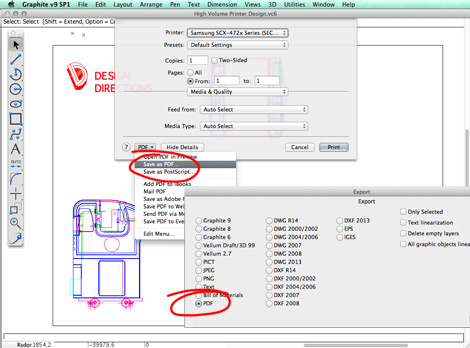
Solution: Use the Export to PDF or the Save to PDF options rather than Print to PDF. But beware: Not all of these are created equal. Sometimes a lazy programmer will say, “Oh we need to export to PDF? I’ll just make a fast pipeline to the Print to PDF,” and the data will be the same low level geometry.
Usually the Save to PDF is a safer option, but you’ll need to try the options to be sure. Of course, Ashlar-Vellum’s Export to PDF maintains the higher order data.
Tessellation During Creation in an Imprecise Modeling Program
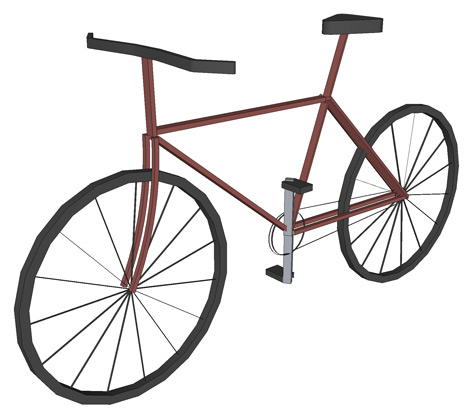
When 3D models are created in imprecise modelers, such as SketchUp or 3D Studio Max, or typically if the model was a 3D scan, their best available data is merely 3D tessellated data. More precise data was unavailable from the beginning.
Solution: The only solution here is to redraw using the 2D drawing or 3D model as a reference for the points need.